12 Projects of Codemas: Day #2 Let's Get Blinky
Adapting PiHut's Raspberry Pi Pico Advent Calendar to Rust and Embassy

Hopefully you already got your project setup ready with Day #1, and now we can continue and make external LEDs light up!
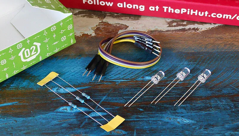
The Day 2 box comes with:
- 1x 5mm Red LED
- 1x 5mm Amber LED
- 1x 5mm Green LED
- 3x 330 ohm resistors
- 4x Male to male jumper wires

The LEDs all look the same, so you won't know which one is which until you plug them in. I got lucky and accidentally put them in the right order, but if you don't, you can unplug the board and reposition them later.
We will be controlling them the same way we did the onboard LED, which is through an Output struct, just for a different GPIO pin.
The LEDs have two legs, one longer than the other, which helps us figure out the polarity because the current can only flow in one direction. The long leg is the Anode (+) and the short leg is the Cathode (-), and current has to always go from positive to negative, so keep a close eye in the later stages once we wire this together.
The resistors help us limit the amount of current that can pass through the circuit, to make sure the LEDs don't draw more power than the GPIO pin can provide, and also protects the LED from getting too much current.
According to the instructions it doesn't matter which side it is on in the circuit, but I will gladly follow their recommendations 😄
For reference, you can double check the Pico Pin Map for which GPIO pins we are using as well.
Construct the Circuit First
Make sure the Pico is diconnected from the USB cable. Apparently we should always have it unplugged whenever we are messing with the circuit, which I guess makes sense.
Breadboard
The breadboard we put the Pico in on Day 1 for the debug probe also allows us to easily wire things together without having to solder it all, which is nice for these sorts of projects.
If you turn the breadboard to the side so that the Pico is on the right, then you can see the red/blue channels on the top and bottom. Apparently all of the holes next to the red line are connected to each other, as are all the blue, but the top and bottom are disconnected. And these create a "rail" of connections for 3.3V on red and Ground (GND) on blue.
The holes in the middle create vertical lines of 5 holes, separated by the divider space in the middle.
The Circuit
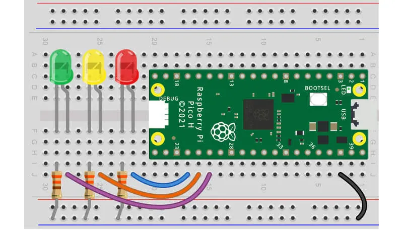
Ok, now we can add the LEDs into the lower half of the middle section of the breadboard. They go one hole apart from each other and the board, with the longest leg to the right (towards the Pico).
Then the resistor should have one side in the vertical lane of the left leg of each LED and the other end in the Ground (blue) lane on the bottom.
Then we need to connect all of the jumper wires. The colors you received may vary, but it doesn't seem to matter which color they are.
Ground: one cable should go from pin 38 on the Pico to the Ground (blue) channel. This is the black cable in the diagram.
LEDs: Each LED should get a cable that has one end in the same vertical lane as the right leg of the LED, and then connected to a GPIO pin. You can use GPIO18 (physical pin 24) for Red, GPIO19 (physical pin 25) for Amber, and GPIO20 (physical pin 26) for Green.
With this, everything should be hooked up and you should be able to plug in the Pico again to flash it with your programs.

Activity 1: Light them up!
First, we can duplicate the Day 1 bin file to day2_lets_get_blinky.rs as a start. The PiHut tutorial for today did a lot to explain loops and variables, things we actually already handled in our Day 1 implementation, so we will actually spend the time to make ours a little more sophisticated.
First things first, instead of having a single output for the onboard LED, we need to create three Outputs and specify the three GPIO pins we used:
//! Light up three LEDs in sequence.

#![no_std]
#![no_main]

use defmt::info;
use embassy_executor::Spawner;
use embassy_rp::gpio::{Level, Output};
use embassy_time::Timer;
use {defmt_rtt as _, panic_probe as _};

#[embassy_executor::main]
async fn main(_spawner: Spawner) {
    let p = embassy_rp::init(Default::default());
    let mut red = Output::new(p.PIN_18, Level::Low);
    let mut amber = Output::new(p.PIN_19, Level::Low);
    let mut green = Output::new(p.PIN_20, Level::Low);

    loop {
        info!("led on!");
        red.set_high();
        amber.set_high();
        green.set_high();
        Timer::after_secs(5).await;

        info!("led off!");
        red.set_low();
        amber.set_low();
        green.set_low();
        Timer::after_secs(5).await;
    }
}
Should look similar, just more blinky!
Overall, this is identical, and you should already be able to run
cargo run --bin day2_blinky --releaseand see some output, and blinking lights!
❯ cargo run --bin day2_blinky --release
   Compiling twelve-days-of-codemas v0.1.0 (/Users/benjamin.brandt/github/twelve-days-of-codemas)
    Finished `release` profile [optimized + debuginfo] target(s) in 1.25s
     Running `probe-rs run --chip RP2040 target/thumbv6m-none-eabi/release/day2_blinky`
      Erasing ✔ [00:00:00] [##################] 12.00 KiB/12.00 KiB @ 81.15 KiB/s (eta 0s )
  Programming ✔ [00:00:00] [##################] 12.00 KiB/12.00 KiB @ 34.21 KiB/s (eta 0s )    Finished in 0.529s
INFO  led on!
└─ day2_blinky::____embassy_main_task::{async_fn#0} @ src/bin/day2_blinky.rs:20
INFO  led off!
└─ day2_blinky::____embassy_main_task::{async_fn#0} @ src/bin/day2_blinky.rs:26
If you realize the colors of your lights don't match up, you can also unplug and rearrange at this point.
Activity 2: Refactor
Ok, coding this, I already felt like we could make the control flow nicer. It seems like it could be error prone to have to always remember to call the commands on every color. So, let's see if we can clean this up a bit.
//! Light up three LEDs in sequence.

#![no_std]
#![no_main]

use defmt::info;
use embassy_executor::Spawner;
use embassy_rp::gpio::{Level, Output};
use embassy_time::Timer;
use {defmt_rtt as _, panic_probe as _};

#[embassy_executor::main]
async fn main(_spawner: Spawner) {
    let p = embassy_rp::init(Default::default());
    let red = Output::new(p.PIN_18, Level::Low);
    let amber = Output::new(p.PIN_19, Level::Low);
    let green = Output::new(p.PIN_20, Level::Low);
    let mut outputs = [red, amber, green];

    loop {
        info!("led on!");
        for out in outputs.iter_mut() {
            out.set_high();
        }
        Timer::after_secs(5).await;

        info!("led off!");
        for out in outputs.iter_mut() {
            out.set_low();
        }
        Timer::after_secs(5).await;
    }
}
Now we put the three outputs into an array, and then within the loop we just iterate over the array twice, once to turn them on and once to turn them off.
This allows us to potentially add more or less LEDs, and the basic algorithm of turning them on and off can stay the same, as now it is just iterating over whatever list is defined.
Activity 3: LED Sequence
Next the goal is to make our LEDs flash one after the other in a sequence, like a festive decoration.
In order to do this, we need to turn one light on and the others off. And here, it is nice to have the outputs already in an array to make the control flow here a bit simpler.
//! Light up three LEDs in sequence.

#![no_std]
#![no_main]

use defmt::info;
use embassy_executor::Spawner;
use embassy_rp::gpio::{Level, Output};
use embassy_time::Timer;
use {defmt_rtt as _, panic_probe as _};

#[embassy_executor::main]
async fn main(_spawner: Spawner) {
    let p = embassy_rp::init(Default::default());
    let red = Output::new(p.PIN_18, Level::Low);
    let amber = Output::new(p.PIN_19, Level::Low);
    let green = Output::new(p.PIN_20, Level::Low);
    let mut outputs = [("red", red), ("amber", amber), ("green", green)];

    let mut i = 0;

    loop {
        // Based on the current iteration, which output should be "on"
        let on = i % outputs.len();

        for (index, (color, output)) in outputs.iter_mut().enumerate() {
            if index == on {
                info!("Flash {}", color);
                output.set_high();
            } else {
                output.set_low();
            }
        }

        Timer::after_millis(500).await;

        i = on + 1;
    }
}
In order to achieve this, I made a few changes. First, I also added a color "label" to each output so that we can log which light is currently flashing.
We then also define i to keep track of the current iteration we are on.
Within the loop, we also calculate on to equal the modulo of the iteration by the length of the outputs. This should always return the index of the light within the list that should be on. And we can use this in the next for loop to decide for each light if we should set it to be "high"/"on" or "low"/"off".
This means, rather than having to code each color on/off for each combination, we can more programmatically figure it out.
In my first attempt, I just had i += 1; as the final line. But then I realized that I don't know what usize is on this board... likely a u32. And with an embedded project, I might leave this running for a long time... and at some point, this value might overflow...
I'm not sure what would happen in this case, so I instead did an optimization where I let the modulo ensure this number never goes above 3, and then it goes back to 1.
Now we can run cargo run --bin day2_blinky --release again and see it blinking:
❯ cargo run --bin day2_lets_get_blinky --release
   Compiling twelve-days-of-codemas v0.1.0 (/Users/benjamin.brandt/github/twelve-days-of-codemas)
    Finished `release` profile [optimized + debuginfo] target(s) in 1.16s
     Running `probe-rs run --chip RP2040 target/thumbv6m-none-eabi/release/day2_lets_get_blinky`
      Erasing ✔ [00:00:00] [###############] 12.00 KiB/12.00 KiB @ 80.29 KiB/s (eta 0s )
  Programming ✔ [00:00:00] [###############] 12.00 KiB/12.00 KiB @ 33.03 KiB/s (eta 0s )    Finished in 0.543s
INFO  Flash red
└─ day2_lets_get_blinky::____embassy_main_task::{async_fn#0} @ src/bin/day2_lets_get_blinky.rs:28
INFO  Flash amber
└─ day2_lets_get_blinky::____embassy_main_task::{async_fn#0} @ src/bin/day2_lets_get_blinky.rs:28
INFO  Flash green
└─ day2_lets_get_blinky::____embassy_main_task::{async_fn#0} @ src/bin/day2_lets_get_blinky.rs:28
INFO  Flash red
└─ day2_lets_get_blinky::____embassy_main_task::{async_fn#0} @ src/bin/day2_lets_get_blinky.rs:28
So cool!
Day #2 Complete!
This was quite fun to actually wire all of this together and get it working. The projects are still quite simple, but it is nice to get a grasp for what a breadboard actually does and how all of this fits together.
As usual, you can see my final implementation on GitHub.


